University of Florida/Egm3520/s13.team1.r2
Report 2
Problem R2.1
Egm3520.s13.team1.stevenchiu (discuss • contribs) 15:28, 6 February 2013 (UTC)
Egm 3520.s13.team1.wcs (discuss • contribs) 15:52, 6 February 2013 (UTC)
Pb-9.1 sec.9 p.9-8. Contents taken from the notes of Dr. Loc Vu-Quoc
Lecture Notes
Problem Statement
Question 1
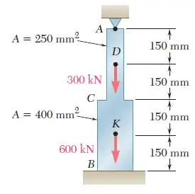
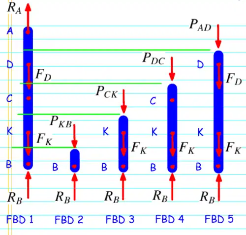
Solve for the reactions at B and at A in the Example 2.04 (see p.9-1) with the stress-strain relation (1) p.9-5.
Solution 1
Given | |||
Applied Forces |
Area |
Length |
Young's Modulus |


Non-Linear Stress-Strain Relation


Free Body Diagrams
- FBD 3:


- FBD 4:


- FBD 5:


Deformation Equations
- Left

- Sub:

- Right

- Sub:

- Total

- ALL E's and L's cancel out


Question 2
Do the results depend on the length of each segment and the Young's modulus?
- Solution 2
While working to determine , which was an equilibrium equation, the resultants were found not to be dependent on segment length or the Young's modulus because both were constants and were subsequently cancelled out. Refer to process above.

Problem R2.2
Problem Number 2.12, p.73. Contents taken from Mechanics of Materials Textbook 6th edition. Authors: F.P BEER, E.R. JOHNSTON, J.T. DEWOLF AND D.F. MAZUREK ISBN:9780077565664
Problem Statement
A nylon thread is to be subjected to a 10-N tension. Knowing that E=3.2 GPa,that the maximum allowable normal stress is 40 MPa, and the length of the thread must not increase by more than 1%, determine the required diameter thread.
Solution
Determine maximum stress allowable with the limit in displacement being :


Derive formula relating area of nylon string with ratio of displacement and original length of the string using these three relations:


Write Area in terms of diameter:

Solve equation for diameter (d):

Problem R2.3
Problem Number 2.16, p.74. Contents taken from Mechanics of Materials Textbook 6th edition. Authors: F.P BEER, E.R. JOHNSTON, J.T. DEWOLF AND D.F. MAZUREK ISBN:9780077565664
Problem Statement
The brass tube AB () has a cross-sectional area of and is fitted with a plug at A. The tube is attached at B to a rigid plate that is itself attached at C to the bottom of an aluminum cylinder (E=72 GPa) with a cross-sectional area of 250mm^2. The cylinder is then hung from a support at D. In order to close the cylinder, the plug must move down through 1 mm. Determine the force P that must be applied to the cylinder.


Solution
Given(s):


Required
Must be moved down 1 mm to find P (force or load required).
Assumptions

To Brass Tube AB


To Aluminum cylinder CD

Total Deflection


Problem R2.4
Problem Number 2.24, p.75. Contents taken from Mechanics of Materials Textbook 6th edition. Authors: F.P BEER, E.R. JOHNSTON, J.T. DEWOLF AND D.F. MAZUREK ISBN:9780077565664
Problem Statement
For the steel truss (E=29*10^6 psi) and loading shown, determine the deformations of members BD and DE, knowin that their cross-sectional areas are 2 in^2 and 3 in^2, respectively.
Solution
Done by method of sections. Cut off the top half of the truss by cutting midway through sections BD, DE and EG.
It is assumed that the structure is in equilibrium.
First


Next


Then


Problem R2.5
Problem Number 2.40, p.89. Contents taken from Mechanics of Materials Textbook 6th edition. Authors: F.P BEER, E.R. JOHNSTON, J.T. DEWOLF AND D.F. MAZUREK ISBN:9780077565664
Problem Statement
A polystyrene rod consisting of two cylindrical portions AB and BC is restrained at both ends and supports and supports two 6-kip loads as shown. Knowing that E=0.45*10^6 psi, determine (a) the reactions at A and C, (b) the normal stress in each portion of the rod.
Solution
We begin by first sketching the free body diagram of the system From this diagram we can see that:
(1)

Next, we consider the deformation of the rod to be zero.
Using equation 2.15 from the text book we see:
(Text 2.15)

Having been given values for all variables in the equation except P we must solve for those two forces. Substituting into the original equation we find:

Calculating the areas gives us:


(2)

Using the equations (1) and (2) we can solve for and


To find the normal stress we simply use formula 1.5 from the first chapter of the text:
(Text 1.5)


Problem R2.6
Problem Number 2.44, p.90. Contents taken from Mechanics of Materials Textbook 6th edition. Authors: F.P BEER, E.R. JOHNSTON, J.T. DEWOLF AND D.F. MAZUREK ISBN:9780077565664 Egm3520.s13.team1.scheppegrell.jas (discuss • contribs) 16:57, 6 February 2013 (UTC)
Problem Statement
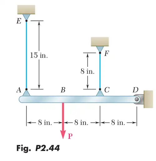
The rigid bar AD is supported by two steel wires of 1/16in diameter (E=29*10^6 psi) and a pin and bracket at D. Knowing that the wires were initially taut, determine (a) the additional tension in each wire when a 120-lb load P is P is applied at B, (b) the corresponding deflection of point B.
Solution
Given | |||
Applied Force |
Area |
Length |
Young's Modulus |
| P=120lb | |||


Solution (a)


Solution (b)


Deflection of point B is approximately

Nomenclature
m = meter
mm = millimeter
d = diameter
G = giga
Pa = Pascal
A = area
Q/P = load
N = Newton
δ = deflection