University of Florida/Egm3520/s13.team1.r6
TEAM 1: REPORT
R6.1: Problem 4.101
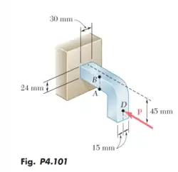
Contents taken from Page 274 in the Mechanics of Materials: 6th Edition textbook. Authors: F.P BEER, E.R. JOHNSTON, J.T. DEWOLF AND D.F. MAZUREK ISBN:9780077565664
- Knowing that the magnitude of the horizontal force P is 8 kN, determine the stress at (a) point A, (b) point B.
Honor Pledge: On my honor, I have neither given nor received unauthorized aid in doing this assignment.
R6.1 Solution
- We must first analyze the cross sectional area.

- Next calculate the moment of inertia of the rectangular cross section.

- Next calculate the centroid of the rectangle

- Next we show a free body diagram of the forces present on the bracket
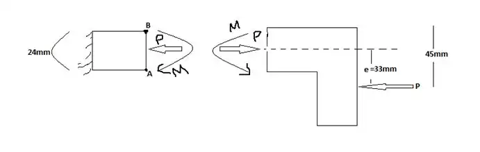
- Find the eccentricity

- Calculate the bending couple using P = 8kN and e = 0.033m

- Now we can calculate the stresses


- Stress induced at point A:

- Stress induced at point B:

R6.2: Problem 4.103
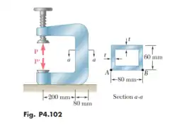
Contents taken from Page 274 in the Mechanics of Materials: 6th Edition textbook. Authors: F.P BEER, E.R. JOHNSTON, J.T. DEWOLF AND D.F. MAZUREK ISBN:9780077565664
- The vertical portion of the press of the press shown consists of a rectangular tube of wall thickness t = 8 mm. Knowing that the press has been tightened on wooden planks being glued together until P = 20 kN, determine the stress at (a) point A, (b) point B.
Honor Pledge: On my honor, I have neither given nor received unauthorized aid in doing this assignment.
R6.2 Solution
Given(s):

- Rectangular cutout is 64 mm x 44 mm


- Stress induced at point A:

- Stress induced at point B:

R6.3: Problem 4.112
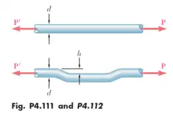
* Contents taken from Page 276 in the Mechanics of Materials: 6th Edition textbook. Authors: F.P BEER, E.R. JOHNSTON, J.T. DEWOLF AND D.F. MAZUREK ISBN:9780077565664. (*) = Reference to listed textbook
- An offset h must be introduced into a metal tube of 0.75 in outer diameter and 0.08 in wall thickness. Knowing the maximum stress after the offset is introduced must not exceed 4 times the stress in the tube when it is straight, determine the largest offset that can be used.
Honor Pledge: On my honor, I have neither given nor received unauthorized aid in doing this assignment.
R6.3 Solution
| Term | Desig | Value |
|---|---|---|
| Outer Diameter | ||
| Thickness | ||
| Inner Diameter | ||
| Area | ||
| Stress |


- The internal forces in the cross section are equivalent to a centric force P and a bending curve M. (*) Ex:4.07 on pg 272
- EQ 4.49 on page 270(*) states:
- (Where F = Force at centroid, P = Line of action load, M = Moment, and d = offset distance.)

- EQ 4.5 on page 271(*) states:

- (Distance from centroid)

- The Moment of Inertia of a Hollowed Cylindrical Cross-Section:

- To ensure the the max stress does not exceed 4 times the stress in the tube and making an assumption that P = 1, we can derive the following solution:


R6.4: Problem 4.114
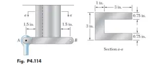
Contents taken from Page 276 in the Mechanics of Materials: 6th Edition textbook. Authors: F.P BEER, E.R. JOHNSTON, J.T. DEWOLF AND D.F. MAZUREK ISBN:9780077565664. (*) = Reference to listed textbook
- A vertical rod is attached at point A to the cast iron hanger shown. Knowing that the allowable stress in the hanger are and , determine the largest downward force and the largest upward force that can be exerted by the rod.


Honor Pledge: On my honor, I have neither given nor received unauthorized aid in doing this assignment.
R6.4 Solution
- Max allowable stresses on the hanger:


- Find centroid:
- Take as a distance measured from left end of shape.


- Due to same parameters,


- Due to same parameters,


- Must incorporate the parallel axis theorem to find moment of inertia:

- b = base, h = height, A = area, and d = perpendicular distance between centroidal axis and parallel axis


- Due to same parameters,

- Total moment of inertia is:


- The normal stress at point A is due to bending:

- "The internal forces in the cross section are equivalent to a centric force P and a bending couple M " (Example Problem 4.07 page 272(*)):
- distance of the force from the centroid of the cross section. (EQ 4.49 page 270 (*))

- Normal stress due to centric load:

- Combine:
- (EQ4.50, p.221(*))

- Total normal stress acting at point A.

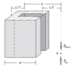
- Largest downward force:
- Assuming conventions: = distance of acting force from the centroid


- Largest upward force:


- The limiting factor is at 7.86 kips force upward.
- Apply negative sign throughout equation:

- The Downward force becomes:


- The Upward Force becomes:


Limit is at

R6.5: Problem 4.115
Contents taken from Page 276 in the Mechanics of Materials: 6th Edition textbook. Authors: F.P BEER, E.R. JOHNSTON, J.T. DEWOLF AND D.F. MAZUREK ISBN:9780077565664
- A vertical rod is attached at point B to the cast iron hanger shown. Knowing that the allowable stress in the hanger are and , determine the largest downward force and the largest upward force that can be exerted by the rod.
Honor Pledge: On my honor, I have neither given nor received unauthorized aid in doing this assignment.
R6.5 Solution
- Max allowable stresses on the hanger:
- Find centroid:
- Take as a distance measured from left end of shape.
- Due to same parameters,
- Due to same parameters,
- Must incorporate the parallel axis theorem to find moment of inertia:
- b = base, h = height, A = area, and d = perpendicular distance between centroidal axis and parallel axis
- Due to same parameters,
- Total moment of inertia is:
- The normal stress at point A is due to bending:
- "The internal forces in the cross section are equivalent to a centric force P and a bending couple M " (Example Problem 4.07 page 272(*)):
- distance of the force from the centroid of the cross section. (EQ 4.49 page 270 (*))
- Normal stress due to centric load:
- Combine:
- (EQ4.50, p.221(*))
- Total normal stress acting at point A.
- Largest downward force:
- Assuming conventions: = distance of acting force from the centroid


- Largest upward force:
- Apply negative sign throughout equation:


Egm3520.s13.Jeandona (discuss • contribs) 12:47, 10 April 2013 (UTC)