University of Florida/Egm3520/s13.team4.r2
Report 2
Problem 2.1
Pb-9.1 in sec.9.
- Indented line
Problem Statement
1)Solve for the reactions at B and at A in the Example 2.04 (see textbook page 72) with the stress strain relation
2)Do the results depend on the length of each segment and the Young's modulus?

Solution
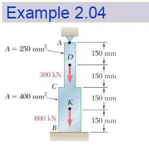
Given:
Length


Area


Young's modulus

Applied forces


Draw a Free Body Diagram for each section
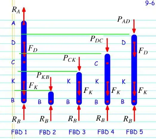
Use on FBD 3


Knowing that the strain relation is found by:
We understand that without a linear strain relation we can't use the superposition principle to separate the reaction as we did in class.
So we'll need to set two FBD's displacement equations equal to each other in order to solve
The displacement equation mentioned previously is applied to FBD 3, which yeilds:
To solve for we must sum all displacements from each section we cut and set it equal to 0
These equations yield


since all quantities are squared, therefore


Problem R2.2
P2.12, Beer 2012
Problem Statement
A nylon thread is to be subjected to a 10-N tension. Knowing that E = 3.2 GPa, that the maximum allowable normal stress is 40 MPa, and that the length of the thread must not increase by more than 1%, determine the required diameter of the thread
Solution
GIVEN:


WE KNOW THAT

AND IT IS REQUIRED THAT


AND WE ALSO KNOW THAT
SO


On our honor, we did this assignment on our own, without looking at the solutions in previous semesters or other online solutions.
Problem R2.3
P2.16, Beer 2012
Problem Statement
The brass tube AB (E = 105 GPa) has a cross-sectional area of 140 mm^2 and is fitted with a plug at A. The tube is attached at B to a rigid plate that is itself attached at C to the bottom of an aluminum cylinder (E = 72 GPa) with a cross-sectional area of 250 mm^2. The cylinder is then hung from a support at D. In order to close the cylinder, the plug must move down through 1 mm. Determine the force P that must be applied to the cylinder.
Solution
Given:
Brass Tube AB:


Aluminum Cylinder DC:


Equations:
Compression of Brass Tube AB:

Tension of Aluminum Cylinder DC:

We know the total deflection:


On our honor, we did this assignment on our own, without looking at the solutions in previous semesters or other online solutions.
Problem R2.4
P2.24, Beer 2012
Problem Statement
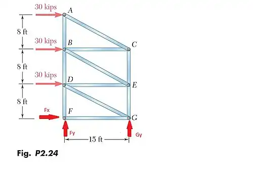
For the steel truss (E = 29 x 10^6 psi) and loading shown, determine the deformations of members BD and DE, knowing that their cross-sectional areas are 2 in^2 and 3 in^2, respectively.
Solution


On our honor, we did this assignment on our own, without looking at the solutions in previous semesters or other online solutions.
Problem R2.5
P2.40, Beer 2012
Problem Statement
A polystyrene rod consisting of two cylindrical portions AB and BC is restrained at both ends and supports two 6-kip loads as shown. Knowing that E = 0.45 X 10^6 psi, determine (a) the reactions at A and C, (b) the normal stress in each portion of the rod.
Solution

Splitting the diagram into two parts we get part 1 and part 2 So we are given:
Part 1:


Part 2:


Looking at the free body diagram we see that

The total equals zero so


Using the formula
We find that

Substituting in the reaction forces and


will show negative because the force is facing opposite to


Solving for we get

So
and solving a system of equations with

Gives


(b) Using the formula

So


On our honor, we did this assignment on our own, without looking at the solutions in previous semesters or other online solutions.
Problem R2.6
P2.44, Beer 2012
Problem Statement
The rigid bar AD is supported by two steel wires of 1 16-in. diameter (E = 29 X 10^6 psi) and a pin and bracket at D. Knowing that the wires were initially taut, determine (a) the additional tension in each wire when a 120-lb load P is applied at B, (b) the corresponding deflection of point B.
Solution


On our honor, we did this assignment on our own, without looking at the solutions in previous semesters or other online solutions.