University of Florida/Egm3520/s13.team5.r2
--Siefman (discuss • contribs) 20:33, 6 February 2013 (UTC)
Problem 2.1 (Pb-9.1 in sec.9.)
On our honor, we did this problem on our own, without looking at the solutions in previous semesters or other online solutions.
Problem Statement
Part 1
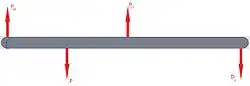
Using Example 2.04(p.9-1), solve for the reaction forces and as if the stress-strain relation is modeled by


(2.1-1)

Part 2
Do the results depend on the length or the Young's modulus of each segment?
Given
(2.1-2)

(2.1-3)

(2.1-4)

(2.1-5)

(2.1-6)

(2.1-7)

Solution
Part 1
Step 1: Draw the free-Body diagram
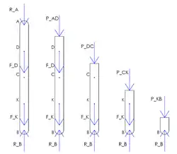
Begin by removing the supports and drawing the free-body diagram for the entire bar AB and the four sections as shown below.
Step 2: Determine the internal forces
Using the internal force, , can be determined in each segment.


(2.1-8)

(2.1-9)

(2.1-10)

(2.1-11)

Step 3: Calculate the displacement
Rearranging Equation 2.1-1,
(2.1-12)

(2.1-13)

The displacement for the whole bar can be represented as a sum of the displacements of each segment and set equal to 0 since both ends of the bar are fixed,
(2.1-14)

(2.1-15)

(2.1-16)

(2.1-17)

(2.1-18)

Substituting the expressions for from above and adding the components together, we receive

(2.1-19)

Step 4: Solve for the reaction at B
can be cancelled out and like-terms can be grouped to give us

(2.1-20)

(2.1-21)

Since , Equation 2.1-21 can be rewritten as

(2.1-22)

|
|
(2.40-13) |

Step 5: Solve for the reaction at A
Referring back the free-body diagram of the entire bar,
(2.1-23)

(2.1-24)

|
|
(2.1-25) |

Part 2
Referring to Equation 2.1-19, can be divided out of both terms and set equal to zero. This confirms that the results do not depend on the length of each segment nor Young's modulus, so long as these values are the same in every segment of the bar.
Problem 2.2 (P2.12, Beer 2012)
On our honor, we did this problem on our own, without looking at the solutions in previous semesters or other online solutions.
Problem Statement
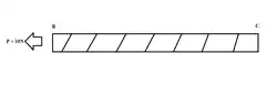
A thread stretching from B to C is subjected to a tension of 10 N. The maximum allowable normal stress is 10 MPa and = 200GPa. The length of the thread may not increase by more than 1%. What is the required diameter of the thread?

Solution
Step One: Determine a relationship between diameter and normal stress and diameter and elongation
The normal stress in the string, , is given by Equation 2.2-1, where is the applied load and is the area.


(2.2-1)

The elongation of the string is given by Equation 2.2-2, where is the elongation of the string, is the length of the string and is the Young's modulus given in the problem statement.


(2.2-2)

The diameter, , can later be inserted into Equation 2.2-1 by equating it to the area, as shown in Equation 2.2-3

(2.2-3)

Step Two: Calculate the diameter if the maximum normal stress is limiting
Inserting Equation 2.2-3 in to 2.2-1 and solving for gives
(2.2-4)

Plugging in the given values from the problem statement,
(2.2-5)

Step Three: Calculate the diameter if the elongation is limiting
First it was assumed that the string had a length of 1 meter, meaning that a 1% elongation would be 0.01 meters. The proportionality of these values is what is important, because their units will cancel later.
Inserting Equation 2.2-3 in to 2.2-2 and solving for d gives
(2.2-6)

Plugging in the given values from the problem statement and the assumed values,
(2.2-7)

Step Four: Choose the smallest diameter
The smallest allowable diameter, and the minimum that is required, occurred when the one-percent elongation was the limiting factor.
|
|
|

Problem 2.3 ( P2.16, Beer 2012)
On our honor, we did this problem on our own, without looking at the solutions in previous semesters or other online solutions.
Problem Statement
A brass tube AB connected at point A, is being applied a load P on top of the tube. At the bottom of the structure is a rigid plate C attached at point B. An aluminum cylinder is hung downwards from point D, and attached to the rigid plate at point C. With the given values, what is the force load, , that is being applied to the brass tube?

Given:
,
,
,


Solution
Step One:Determine the deflection on the brass tube
First step is to analyze the brass tube at point A and B.
At the segment AB, the brass tube experiences a state of compression when the load is applied at point A.
(2.3-1)


In order to find the load applied to the brass tube, a relation between the cylinder and the tube has to be made through the equations of deflection. For the brass tube the deflection is:
(2.3-2)

After substituting the given values from the problem statement:
(2.3-3)
(2.3-4)


Step Two:Determine the deflection on the aluminum cylinder
Next, is to find the deflection that is created by the load at point A, on the aluminum cylinder collected at point D. The deflection of the aluminum cylinder hanging at point D.
The deflection of the aluminum cylinder is measured by the following equation:
(2.3-5)

After substituting the values given in the above problem statement, the equations looks like the following:
(2.3-6)

(2.3-7)

Step 3 (Finding the stress load)
Total deflection is as followed:
(2.3-8)

(2.3-9)

|
|
|

Problem 2.4 ( P2.24, Beer 2012)
On our honor, we did this problem on our own, without looking at the solutions in previous semesters or other online solutions.
Problem Statement
Determine the deformations of members BD and DE in the steel truss ( = 29 E6 psi) shown in Figue 2.4-1. Their cross-sectional areas of BD and DE are 2 in^2 and 3 in^2 respectively. The steel truss is shown in Figure 2.4-1

Given:


Solution
Step One:Draw a free-body diagram of the system
The free-body diagram is shown in Figure 2.4-2.

Step Two: Use the equilibrium of moments and forces at point F
The sum of moments around point F is zero and the counterclockwise direction is taken as positive.
(2.4-1)
![{\displaystyle \displaystyle \Sigma M_{F}=0=G_{y}\times 15ft-30kips\times [8ft+16ft+24ft]}](../../../I/7871e243837e33a0186ed67d4fe3b5556f6419e1.svg)
Solving for gives,


The sum of forces in the y-direction is also zero.
(2.4-2)

Therefore, is


The sum of forces in the x-direction is also zero.
(2.4-3)

Therefore, is


Step Three: Isolate the truss at FDG and solve for the forces
First, a free-body diagram must be made for the isolated truss FDG.

To solve for , take the sum of the forces in the x-direction, which is zero.

(2.4-4)

Knowing from Step Two, is

Next, the sum of the moments about G is take, which also equals zero.
(2.4-5)

Therefore, is


Step Four: Solve for the deformation of members BD and DE
The deformation of members BD and DE are given by Equations 2.4-6 and 2.4-7, respectively.
(2.4-6)

(2.4-7)

Solving for and with the given and calculated values gives


|
|
|

|
|
|

Problem 2.5 ( P2.40, Beer 2012)
On our honor, we did this problem on our own, without looking at the solutions in previous semesters or other online solutions.
Problem Statement
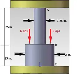
A Polystyrene rod consisting of two cylindrical portion AB and BC is restrained at both ends ans supports two 6-kips loads as shown. Knowing that , determine the reactions at A and C, and the normal stress in each portion of the rod.

Solution
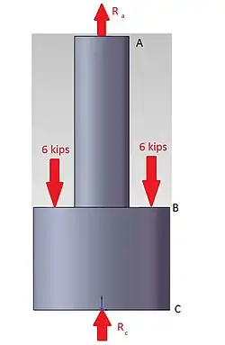
Step One:Find the reactions at A and C
The elongation of the rod is zero.
(2.40-1)

The forces are equal in opposite directions.
(2.40-2)

(2.40-3)

By substitution and simplifying the elongation of the rod can be rearranged to solve for in terms of


(2.40-4)

(2.40-5)

(2.40-6)

From the free body diagram the sum of
totals to 12 kips.

(2.40-7)

After substitution and simplifying the reactions can be calculated.
(2.40-8)

(2.40-9)

|
|
(2.40-10) |

|
|
(2.40-11) |

Step Two:Calculate the normal stress for both members
The normal stress for the member equals the stress divided by the area of the members. After substitution these normal stresses can be calculated.

(2.40-12)
|
|
(2.40-13) |


(2.40-14)
|
|
(2.40-15) |

Problem 2.6 ( P2.44, Beer 2012)
On our honor, we did this problem on our own, without looking at the solutions in previous semesters or other online solutions.
Problem Statement
The rigid bar AD is supported by two steel wires of in. diameter psi) and a pin and bracket at D. Knowing that the wires were initially taut, determine (a) the additional tension in each wire when a 120-lb load P is applied at B, (b) the corresponding deflection of point B.


Solution
Step One:Draw the free-body diagram
Let be the rotation of the bar ABCD.

(2.44-1)

(2.44-2)

(2.44-3)

(2.44-4)

(2.44-5)

(2.44-6)

(2.44-7)

(2.44-8)

Using the free body diagram ABCD the sum of the momentum is equal to 0.
(2.44-9)

(2.44-10)

(2.44-11)

Substituting into these equation give the tensions in each wire.
|
|
(2.44-12) |

|
|
(2.44-13) |

The deflection of the beam is the angle of the moment multiplied by the length of the beam (16in).
|
|
(2.44-14) |

Contributors
Team Designee: Daniel Siefman
Table of Assignments | ||
| Problem Number | Solved by |
Reviewed by |
2.1 |
Tim Shankwitz and Gregory Grannell | All |
2.2 |
María José Carrasquilla and Daniel Siefman | All |
2.3 |
Michael Lindsay and Joshua Herrera | All |
2.4 |
Michael Lindsay and Daniel Siefman | All |
2.5 |
Andrew Moffatt and Phil D Mauro | All |
2.6 |
Andrew Moffatt and Phil D Mauro | All |
References
Beer, F. P., Johnston, E. R., Jr., DeWolf, J. T., & Mazurek, D. F. (2012). Mechanics of materials (6th ed.). New York, NY: McGraw Hill.